Relativity™
Electrostatic Subframing System
The IDES RELATIVITY Electrostatic Subframing System multiplies the frame rate of cameras on JEOL TEMs. Microscopes equipped with RELATIVITY achieve exceptional time resolution, data throughput, and advanced automation capabilities.
How it works
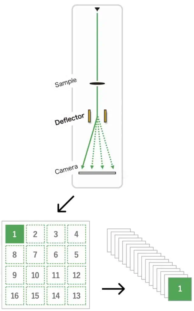
RELATIVITY installs an electrostatic optics assembly in a wide-angle camera port. These optics rapidly deflect the image data to different regions (or subframes) of the camera in a programmable sequence. Each camera readout contains a tiled array of crisp, blur-free subframes. Raw data is automatically analyzed to give a stack of images.
Features at a Glance
Time resolution
RELATIVITY performs transitions between subframe regions in less than 100 ns.
Continuous kHz-scale video
RELATIVITY can sustain subframe rates up to 100 kHz.
Custom applications
Integrate RELATIVITY with an in situ holder, laser, IDES Electrostatic Dose Modulator, or other accessories.
Out of sight, out of mind
Optics pneumatically retract out of the beam when they are not in use.
Acuity Edge analysis server
Automated segmentation and alignment helps you get the most out of your data.
Advanced control software
Seamlessly move between measurement programs with our intuitive interface, or use our powerful tools to design something new.
Simple field installation
RELATIVITY’s electrostatic optics are installed through an side-mounted camera port.
Performance
| Standard configuration (SD)(1) | Imaging filter configuration (IF)(1) | |
|---|---|---|
| Image sensor location | Bottom camera chamber | After imaging filter |
| Relativity deflector module install location | Side-mounted camera port(2) | Side-mounted camera port(2) |
| Subframe transition time | < 100 ns | < 50 ns |
| Minimum subframe exposure | 500 ns | 250 ns |
| Maximum subframe rate (continuous) | 100 kHz | 300 kHz |
| Maximum subframe size on camera | 7 mm × 5.3 mm(3) 460 × 350 pixels (by Gatan OneView®) | n/a(4) |
| Native subframe array layout (no overlap)(3)(4) | 8 × 10 at 200 kV or lower, 7 × 8 at 300kV (by Gatan OneView®) | n/a(4) |
| Subframe array layouts(3)(5) | 200 kV: 8 × 10, 11 × 11, 12 × 12, 13 × 13, 14 × 14, 15 × 15 300kV: 7 × 8, 9 × 9, 10 × 10, 11 × 11, 12 × 12 (by Gatan OneView®) | 200 kV: 4 × 4, ..., 10 × 10 300 kV: 4 × 4, ..., 14 × 14 |
| Auxiliary logic outputs Quantity Sample rate | 4 × TTL-compatible outputs 125 MS/s (MS: mega sampling) | 4 × TTL-compatible outputs 125 MS/s (MS: mega sampling) |
| Trigger input | 1 × TTL-compatible input | 1 × TTL-compatible input |
(1) Select one of these configurations to order. Custom configurations can be made available on request.
(2) In the JEM-2100Plus, RELATIVITY deflector module is installed in the left-side STEM detector port.
(3) The subframe size for SD configuration is limited by the spacing between deflector electrodes (the ‘deflector gap’). Detailed information is available in the specification sheet of RELATIVITY.
(4) The subframe size for IF configuration is limited by a circular aperture installed on the top of RELATIVITY deflector module. The subframe sizes are also affected by imaging conditions.
(5) Due to geometrical constraints, different subframe array layouts are optimal for different detector sizes. Gatan OneView® camera is chosen for illustrative purposes. RELATIVITY system is compatible with nearly all commercially-available cameras
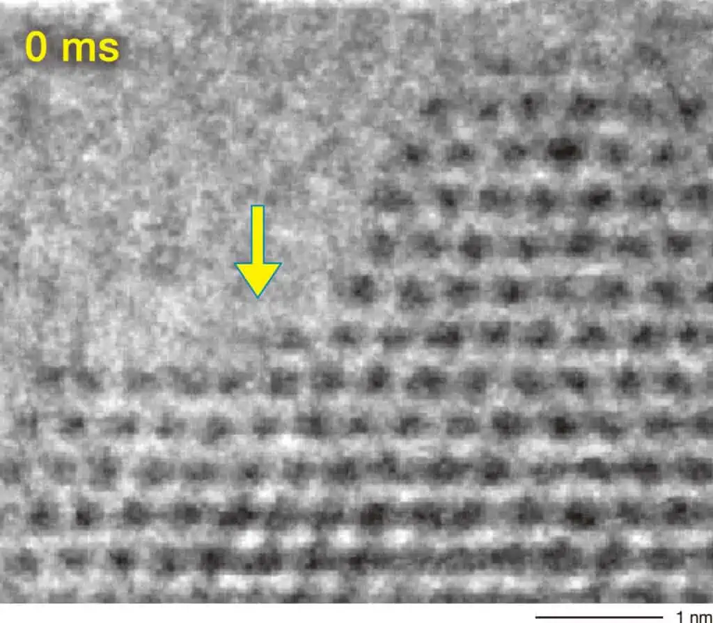

This data shows TEM images of a CeO2 surface acquired with 0.82 ms exposure time.
As shown in the TEM image on the right, the Ce atoms have migrated after 4 ms. (Instrument: JEM-ARM300F2, Accelerating Voltage: 300 kV)
Sample courtesy of Johnson Matthey, UK
Applicable Models
- JEM-ARM300F/300F2
- JEM-ARM200F
- NEOARM
- JEM-F200
- JEM-2100Plus